Agriculture
Digitization of CAD Data for Hydraulic Equipment
The client is a New Zealand-based leading manufacturer and supplier of hydraulic systems and components for OEMs. They built custom and off-the-shelf hydraulic cylinders. They have a vast market scope around Oceania and the USA.
Scope
The customer required assistance in the design of a novel hydraulic cylinder tailored for a specific application within the agriculture industry. Initial design ideas were outlined on paper and presented in the form of 2D drawings.
The client sought us to convert these 2D representations into comprehensive 3D models suitable for analysis, simulation, and smooth manufacturing.
Challenge
Key challenges in designing a hydraulic cylinder from 2D drawings included:
- Interpreting 2D Details: The original 2D drawings provided a solid foundation but lacked critical manufacturing details like seal groove dimensions, bore tolerances, and surface finishes. These had to be carefully and accurately defined in 3D to ensure proper functionality and avoid sealing or alignment issues.
- Managing Tolerance Stack-Up: A major challenge was to ensure that all moving components, like piston, rod, and end caps, fit together precisely. While tolerances were assigned in 2D, their cumulative effect became clear in 3D.
- Adapting the Design for Manufacturing: Certain features like deep internal grooves, sharp corners, and complex port placements needed adjustments to ensure they could be easily machined and assembled without excessive cost or custom tooling.
- Ensuring Structural Strength & Performance: The hydraulic cylinder needed to withstand high pressure and repeated load cycles. We had to identify potential weak points and optimize the wall thickness, reinforcement, and weld joints to prevent fatigue failure.

Solution
Leveraging our expertise in CAD conversion services, we systematically gathered all input data, categorizing them to develop an effective project plan. This structured approach helped us deliver high-quality outputs within the scheduled timeline, ensuring a smooth transition from 2D to 3D.
Here’s how we made it happen:
Accurate CAD Conversion
Using SolidWorks, we converted the 2D drawings into detailed 3D models, making sure every part was properly defined for manufacturing. To ensure accuracy, we:
- Refined bore tolerances, seal groove depths, and surface finishes to meet industry standards.
- Applied GD&T (Geometric Dimensioning & Tolerancing) for precise fits, ensuring proper assembly and function.
- Validated seal compatibility using supplier catalogs and engineering calculations to prevent leakage and performance failures.
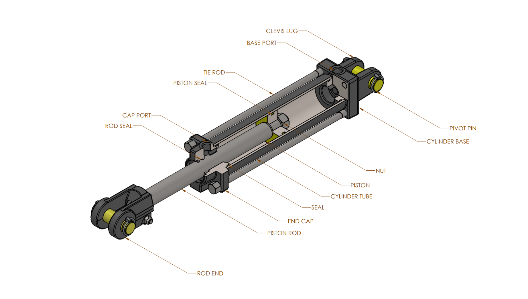
Designing Complex Internal Components
The hydraulic cylinder contained intricate geometries and complex internal elements, such as pistons, seals, ports, and hydraulic chambers. All of these needed to fit and function perfectly. To get it done, we:
- Modeled each internal component separately and then assembled them to ensure everything worked together smoothly.
- Used advanced 3D modeling techniques to check how the parts would move in real-world conditions.
- Created section views and exploded models to double-check clearances and make sure everything fit as expected.
Design for Manufacturability
To ensure the hydraulic system was designed for easy to manufacture, we:
- Optimized deep grooves and sharp edges to make machining easier.
- We selected standard materials like ANSI 1045 steel, U400-15 cast iron, and ANSI 1040 steel to ensure the hydraulic cylinder is durable, strong, and cost-effective.
- We designed components to follow ISO standards, making manufacturing, maintenance, repairs, and future replacements easier.
Design Iteration & Quality Checks
Before finalizing the design, we went through multiple iterations, incorporating feedback from the client’s cross-functional team.
To ensure top quality, we conducted:
- FEA (Finite Element Analysis) in SolidWorks to validate durability and real-world performance.
- Tolerance analysis to prevent leaks, misalignment, or premature wear.
- Assembly checks to confirm proper fit and function.
Finally, thorough assembly and part drawings, including a comprehensive bill of materials (BOM), were generated to streamline the manufacturing process.
Sedin converted the legacy data into the required CAD format while ensuring compatibility with the client’s software. With a structured project plan and strict quality checks, we delivered accurate and ready-to-use files.
Value and Benefits
The successful CAD conversion brought about transformative changes in the client’s engineering division, and intellectual properties were preserved efficiently.
The client experienced reduced lead times in implementing design changes, resulting in faster responses to market demands and customer feedback.
The design teams experienced improved collaboration, as the converted data was seamlessly integrated with modern CAD tools.
A validated and manufacturing-ready design improved durability, minimized rework, and made installation hassle-free.
With a proven design process, we delivered cost-effective solutions with exceptional quality on time.
Related Case Studies


Container Design for Battery Energy Storage System (BESS)
Learn how we optimized design of a battery storage system container to reduce weight, ensure structural integrity, and achieve efficient thermal regulation.


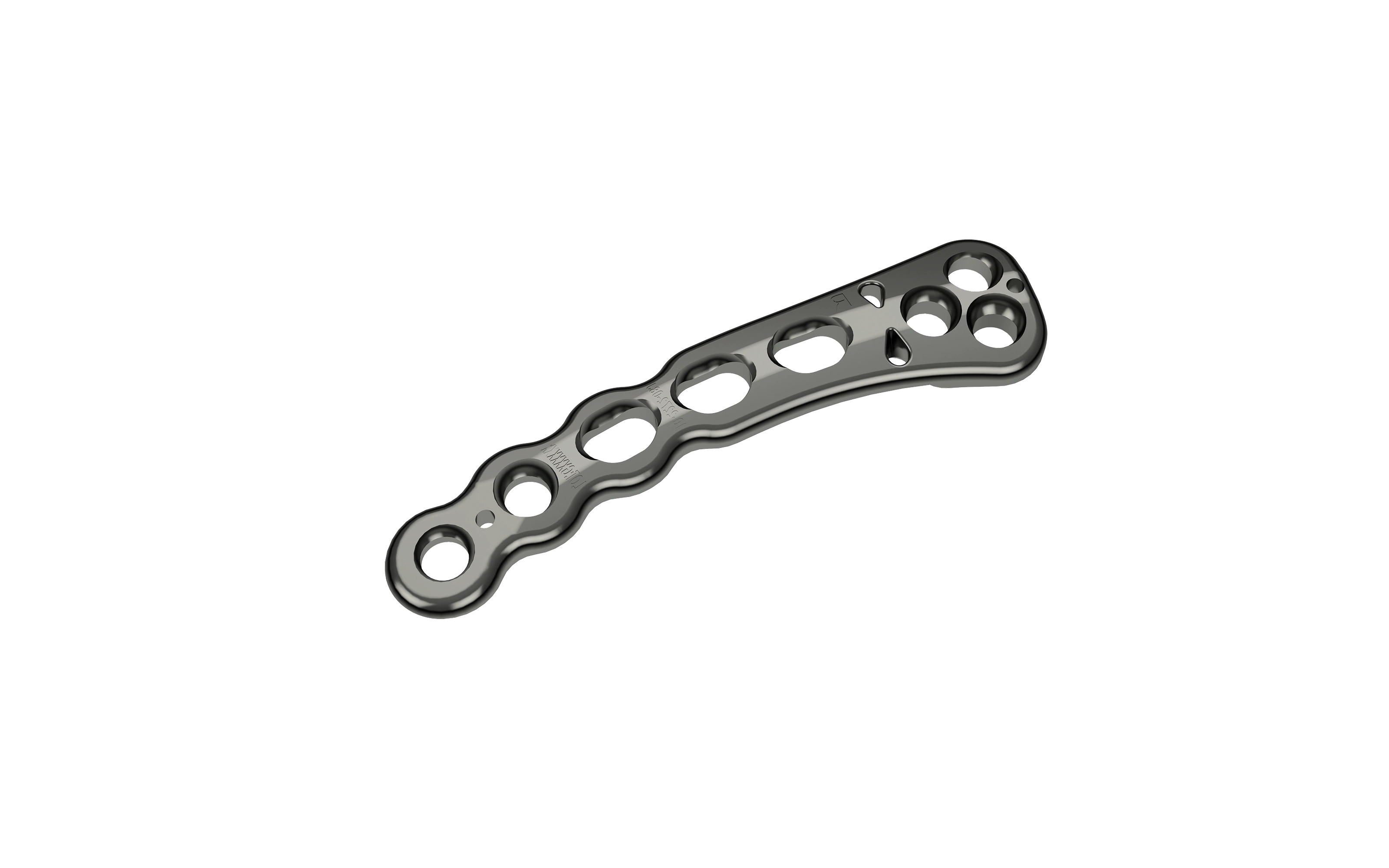
Legacy Data Migration for Orthopedic Implant Design
Modernizing legacy data for pediatric orthopedic implants with scalable 3D models, ensuring regulatory compliance, and improving surgical outcomes in the medical industry.