- Creating 3D parametric designs using client-provided Mechanical Datasheets, TDS, and specific process requirements.
- Detailed design of shell and tube heat exchanger including material selection, manufacturing process planning, 3D CAD modeling, 2D manufacturing drawings, etc.
- Creation of auxiliary items like test heads, ship loose kits and a complete Bill of Materials (BOM).
- Product Lifecycle Management (PLM) to ensure traceability, version control and design consistency throughout engineering iterations.
Oil & Gas
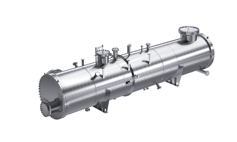
Shell and Tube Heat Exchanger Design
The client is one of the leading Alberta-based and globally recognized designers and manufacturers of shell & tube and air-cooled heat exchangers within the natural gas, oil and petrochemical industries. They have a wide range of markets in various locations around Canada, USA and Europe.
Scope
Challenge
Designing a heat exchanger for a real-world process environment comes with several technical complexities. In this project, we encountered:
- Handling corrosive fluids: The shell side carried a hydrocarbon-based fluid that was corrosive, so we had to carefully choose materials that would last and resist damage over time.
- Compact space constraints: The heat exchanger needed to fit into an existing plant setup with limited space, which restricted the size, shape, and nozzle placement.
- Low pressure drop, high efficiency: Both fluids had to flow efficiently with minimal pressure loss (below 0.2 bar) while still achieving high heat transfer performance.
- Strict documentation requirements: All design files, drawings and BOMs had to follow the client’s specific quality standards and be compatible with their PLM system.
Solution
Leveraging our expertise in product design engineering services, our team designed a custom shell and tube heat exchanger that met the client’s performance, space and maintenance requirements.
We used advanced CAD tools like AutoCAD and Autodesk Inventor to create accurate 3D models. These designs were based on the client’s Mechanical Datasheets, Technical Data Sheets (TDS) and project-specific needs. Our goal was to deliver a solution that was strong, efficient, and easy to manufacture.
Here’s how we approached it:
1. 3D Parametric Modeling
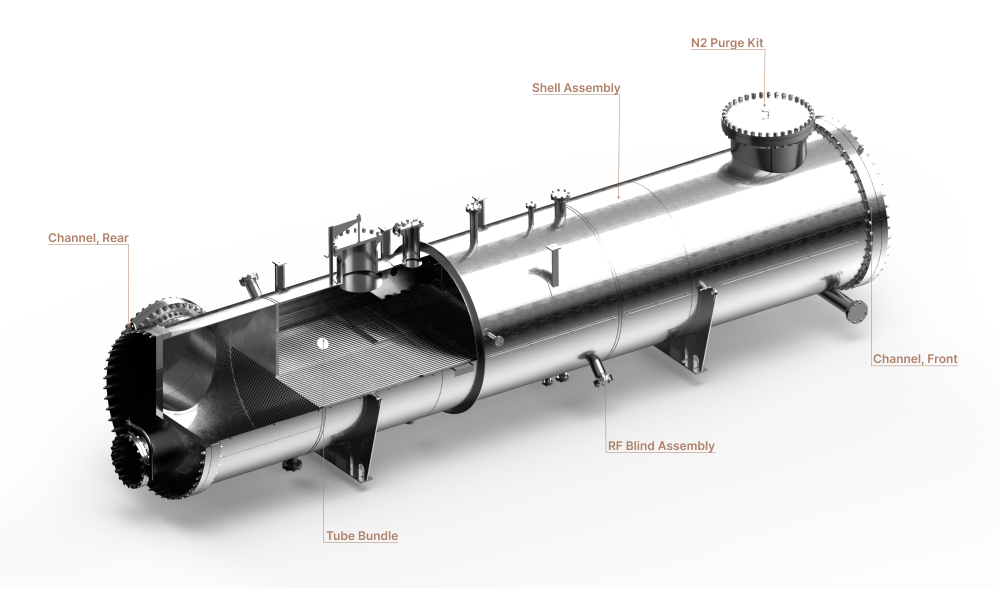
Our shell and tube heat exchanger design process began with creating fully parametric 3D models of the shell and tube using Autodesk Inventor. This allowed us to quickly update the model whenever the specifications like tube length, pitch, or layout changed, without redoing the entire design.
We ensured the 3D models matched the actual size and shape of the parts, with proper clearances for assembly. They were designed to follow ASME Section VIII and TEMA standards. As the models were parametric, we could easily create accurate drawings and BOMs from them.
2. 2D Manufacturing Drawings
From the 3D model, we generated fully detailed 2D manufacturing drawings including:
- General Arrangement (GA) drawings
- Weld maps and section views
- Detailed drawings of baffles tubesheets and nozzles
- Tolerances, material specifications and surface finishes
These drawings served as the reference for the fabrication shop, ensuring a smooth transition from design to manufacturing.
The drawings followed ISO and ASME Y14.5 standards, which helped the client achieve accurate manufacturing and smooth inspection.
3. Material Selection
Based on the client’s requirements and the corrosive nature of the fluids, we selected materials that balanced mechanical strength, corrosion resistance, and thermal performance.
- Tube bundle: SS316L stainless steel for its excellent corrosion resistance and durability in hydrocarbon service.
- Shell: SA-516 Gr. 70 carbon steel, selected for its strength and cost-effectiveness.
- Gaskets & fasteners: Specified to suit high-temperature, corrosive conditions.
All materials complied with ASTM and ASME standards and were selected in line with the client’s material traceability and certification requirements.
4. Manufacturing Process Planning
With our deep understanding of manufacturing, we identified and proposed the most suitable process for the heat exchanger. This involved choosing fabrication methods, welding techniques and quality control measures.
Here’s what we planned:
- Shell fabrication: Rolling and welding the shell using certified welders.
- Tube bundle assembly: Inserting tubes into the tube sheet, then expanding or welding them depending on the design.
- Welding methods: Used GTAW (TIG) welding for stainless steel and SMAW for carbon steel parts to ensure strong, clean welds.
- Testing & quality control: Included hydrotesting, dye penetrant testing (DPT), and radiography as needed.
All steps followed industry standards and were documented for quality assurance and client approval.
5. Thermal and Mechanical Optimization
Once the design and material were finalized, we conducted both thermal and mechanical optimization to ensure the heat exchanger delivered reliable performance.
Our thermal analysis verified heat transfer efficiency, pressure drops, and confirmed that the outlet temperatures met the client’s requirements. We also checked for even flow distribution across the tubes to avoid hotspots or performance issues.
On the mechanical side, we assessed stresses on the shell, tubes, and nozzles using ASME standards. We also reviewed baffle spacing to prevent tube vibration and confirmed the structural integrity of the design under expected pressure and temperature conditions. These checks ensured that the final product was both efficient and robust.
6. Complete Manufacturing Doumentation
We prepared all essential deliverables for smooth manufacturing and assembly. This included:
- Test Heads that simulate real-world conditions for quality testing. This included provisions for pressure testing, material analysis and other relevant tests.
- Bill of Materials (BOM) that lists all components required for the heat exchanger. We also ensured that the BOM is linked to the 3D model and manufacturing drawings.
- Ship Loose Kit that includes all loose items to be shipped with the heat exchanger like gaskets, bolts and other accessories. This kit facilitates easy assembly and installation.
7. Product Data Management (PDM)
Using Autodesk Vault, we managed the entire design lifecycle. The system included:
- Version control: Manage different versions of designs and documents to track changes and updates.
- Document management: Store and organize all design documents, datasheets, and technical specifications.
- Collaboration tools: Facilitate collaboration among team members and stakeholders throughout the product development process.
8. Quality Assurance and Compliance
Our team implemented a robust quality assurance system aligned with Sedin’s internal checklist, client requirements and all relevant industry standards. This ensured full compliance and reliable performance throughout design and manufacturing.
Value and Benefits
With parametric modeling, the client could accommodate design changes (like tube layout or dimensions) without delays. This reduced turnaround time significantly.
Our comprehensive 2D manufacturing drawings facilitated a streamlined manufacturing process, reducing production time and costs.
ASME- and ASTM-compliant materials validated welding processes and QA/QC steps ensured the final product met high performance and safety standards.
Complete manufacturing documentation, test heads, ship loose kit and PDM systems gave the client everything needed for seamless manufacturing and lifecycle management.
The clear process flow, quality controls and accurate deliverables helped reduce rework, material waste and long-term maintenance issues.
Related Case Studies


Designing Bale Grab Attachment for Skid Steers
Designed a custom bale grab attachment for skid steers, improving performance, reducing costs and streamlining processes for the agriculture industry.


Container Design for Battery Energy Storage System (BESS)
Learn how we optimized design of a battery storage system container to reduce weight, ensure structural integrity, and achieve efficient thermal regulation.


Advanced Tillage Unit Design – Agricultural Machinery
Designed a durable, versatile tillage unit - an advanced agricultural machinery meeting Australian, U.S., and European standards for various soils and tractors.